When tuning for larger injectors, don’t go messing with the Mass Air Flow (MAF) table, or this could happen.
Closed Loop Fueling
First, some background information on how the Subaru ECU controls Air-to-Fuel Ratio at low load (idle, low throttle, cruising) where AFR is kept at ~14.7:1
- Mass Air Flow (MAF) sensor measures amount of air going into the engine.
- ECU calculates duration to open the fuel injectors based on injector flow rate, MAF reading, and desired AFR (14.7)
- Resulting AFR is measured by an Oxygen sensor in the exhaust manifold.
- If the actual AFR is higher than intended, injector spray time is increased, if AFR is lower than intended, spray time is reduced.
- Over time, these corrections are stored as a preset of sorts, to help achieve 14.7 AFR quicker. These correction values are called Long Term Fuel Trims (LTFT)
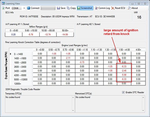
- There are four Long Term Fuel Trim that covers different ranges of air flow rates. The last one is usually for rates greater than 40 or 50g/s. This is the important one, as will be shown below.
Open Loop Fueling
When you apply full throttle the ECU will transition to Open Loop Fueling where the injector pulse duration is calculated solely from MAF readings,the Fuel Enrichment table (desired AFR), and the LTFT value that has been stored for the last flow range (i.e. >40 or 50g/s). The Oxygen sensor data is no longer used (because it is not accurate under these conditions) as a feedback mechanism to correct for errors in the final AFR. If the value of LTFT is -10% then the injector pulse width calculated from MAF and desired AFR is further reduced by 10%.
The implication of the above is that, if the MAF table is incorrect near, and only near 50g/s, it will develop a value for the LTFT that is not applicable for the rest of the MAF table.
Adding Larger Injectors
So, what happens when you install injectors with higher flow rate? Without changing anything in the ECU, the same pulse width would be calculated from the MAF readings but the fuel delivered would be more than before. In Open Loop operation, this would mean the AFR will be lower than intended. How do you correct this over-fueling? The logical method would be to tell the ECU that the injector flow rate has increased so that it can calculate the proper pulse width to use. An alternate method is to alter the MAF table. By scaling the values in the MAF table down, the ECU will also end up using lower injector pulse width because it thinks there is less air coming into the engine then the actual amount.
Where is the problem then?
While it is possible to achieve the desired Open Loop AFR by scaling the MAF table, it has to be done across the entire flow range of the MAF table. Since Open Loop AFR is usually collected under high boost conditions, the low flow area could be overlooked, which was the case for the car that produced the above snapshot, showing high amount of knock and negative fuel trim.
If the MAF table is left with stock values near 2.7V (~50g/s), in closed loop operation, the ECU would have to reduce the pulse width in order to maintain 14.7 AFR, eventually leading to negative values for LTFT. As it take time to set the LTFT, it would stay at 0% while testing is being done at full throttle.
So, after the MAF table is manipulated to produce, say, 11:1 AFR under full boost, with LTFT of 0%, the value of LTFT will set over time to a negative value. The amount would depend on the difference in flow rate between the original and the new injectors. For example, if the original injectors are 420cc/min and the new ones are 550cc/minute, the flow rate changed by ~30%. In theory, LTFT would drift to -30% in order to compensate for the injectors. However, the WRX ECU limits the range of values for LTFT to +/-15%. In the above screen shot, the value of LTFT at 50+ g/s is -14.99%, the maximum that the ECU allows.
With LTFT at -15%, the calculated pulse width that was necessary to achieve 11:1 AFR in boost is now being reduced by 15%, which means the AFR will now be ~12.6:1, much too lean to support the ignition advance being used and causes detonation. In response to this, the ECU has to reduce ignition advance to stop the detonation. The numbers highlighted in the above screen shot indicate the amount of ignition advance that the ECU is removing to combat detonation caused by the lean AFR.